I've read the PA bias study from Hans and tried to tweak the PA of my U3S for optimum harmonics suppression etc. The spectrum is measured using an SIGLENT SSA3021X analyzer. The power is measured using a 40dB tap and a cheap 20w Dummyload from Diamond: 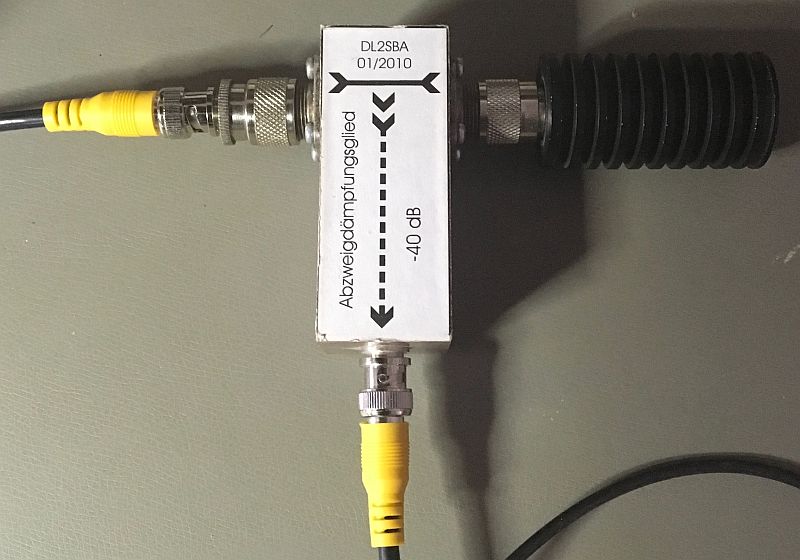 The tap is based on the work of OZ2CPU.
Bad power supply
Here the spectrum plots for a bias voltage of 2.2VDC and a PA voltage of 10VDC. The numerical data can be viewed in this XLS-file.

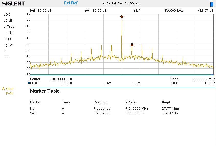
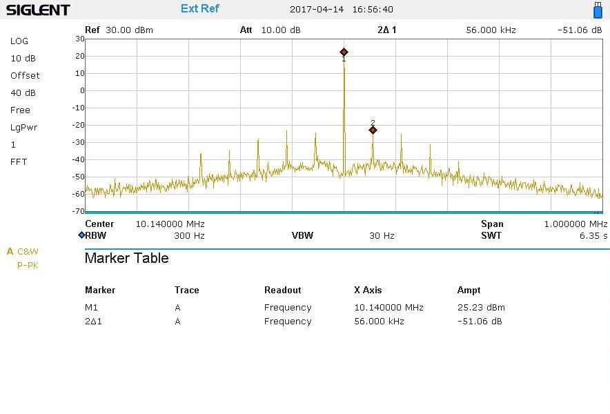
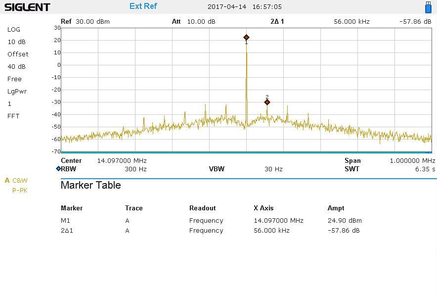
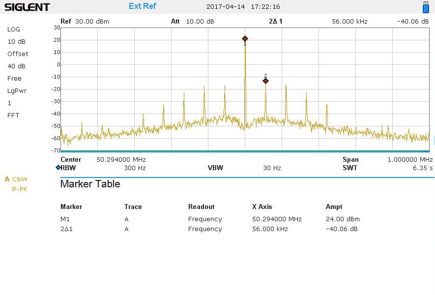
As can be seen, there are spurious emissions between -40dBc and -59dBc - more or less matching the regulatory specs - but in 56kHz spacing?
Comments on the QRPLabs group pointed me to the power supply. I've used two different voltage regulators. One for the 5VDC rail of the U3S and one for the 10VDC PA rail of the U3S. The regulator for PA rail is a linear LM317 based one. The regulator for the 5VDC rail is a cheap LM2596 based switch-mode DC-DC converter.
Improved power supply
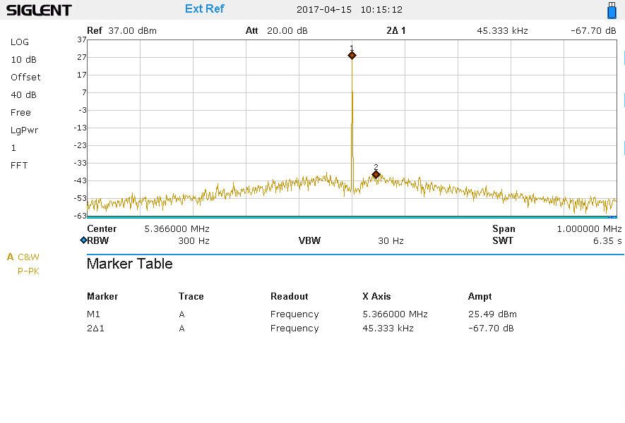
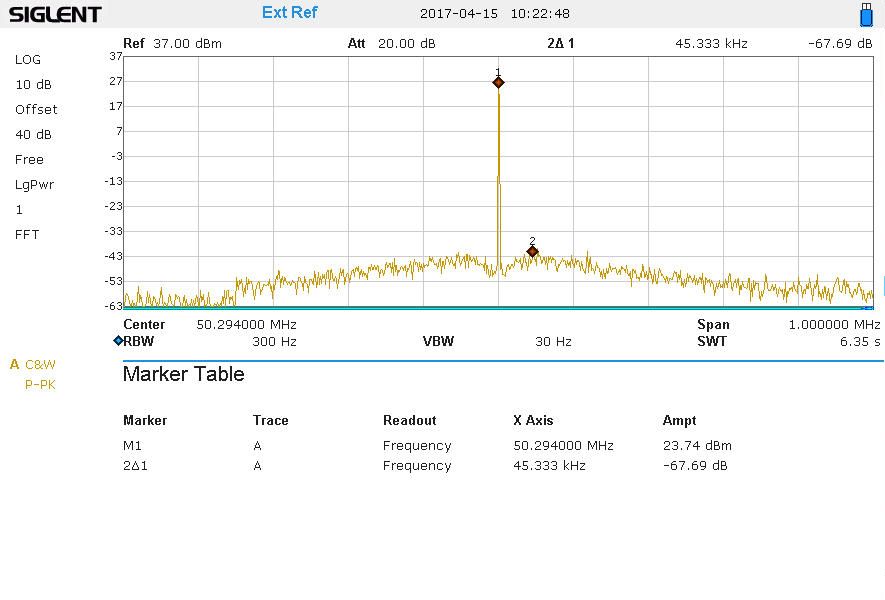
I've changed the switch-mode DC-DC converter to a second linear LM317 based one and the spurious emissions are gone :-) please see the plots below.


Now I have the issue, that some power has to be dissipated to the ambient air. My U3S draws about 150mA on the 5VDC rail. Feeding the complete rig with 13.9VDC gives 13.1VDC after the reverse polarity protection diode. This leads to a power dissipation of
( 13.1VDC - 5VDC ) * 0.15A = 1.2W
The Junction-to-ambient thermal resistance for the LM317 in TO220 case is 38°C/W. With an ambient temperature of 22°C gives a junction temperature of
( 38°C/W * 1.2W ) + 23°C = 69°C
This is a safe distance from the allowed 125°C for the LM317.
For the unknown small heat sink on the regulator board I assume 30°/W. This leads to a temperatur of the heat sink of
( 30°C/W * 1.2W ) + 23°C = 59°C
Using a thermo couple to measure the temperature of the heat sink gives 66°C. So I assume the heat sink is much worse - hm.