The electronics for my capacitive (water) level sensor is described here. In this article I will go a little bit in depth regarding the sensor reading and value compensation.
Electrodes
I've build two capacitive probes - one with a coaxial electrode and one with a twin-wire electrode.
Coaxial electrode
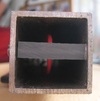
This electrode consists of a rectangular aluminium tube of 30mmx30mm with a single wire u-shaped inside the tube.
U-shaped wirde bottom of electrode:
For this electrode, the tube is grounded. The electrode should be connected to the sensor board using a coaxial-cable.
Twin-wire electrode
Another electrode I've built is using a simple two-pole speaker wire. 
Measurement basics
As described in Nathan Hurst's work, the electrode forms a capacitors with variable capacity based on the level of coverage by the medium (in my case rain water).
In my application I've no interest in absolute capacity values - I want to measure the relative water level inside a water tank. Here only the relative filling is of interest.
Based on the formulas from Wikipedia  for a plate-type capacitor and
  for a tube-type capacitor, the capacity is dependent of the size of the capacitor but also on the permittivity of the dielectricum.
Unfortunately the permittivity of water is highly dependant on its temperatur. Usually you find discrete values for water i.e. 0°C, 10°C, ... but this coarse steps are not usable for sensor calibration. So I checked the internet for further data and found these two sources:
- Calculation of the permittivity using a simple formula. This formula depends on the density of water which also highly temperature dependent.
- Calculating water density can be done using this Spreadsheet for a number of discrete values
Based on these two sources, I've build my own spreadsheet giving me a compensation table for water between 0°C and 100°C. The XLS-sheet can be downloaded here.
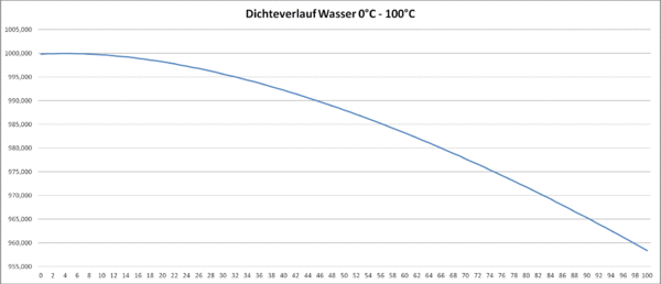
This results in a density graph for water:
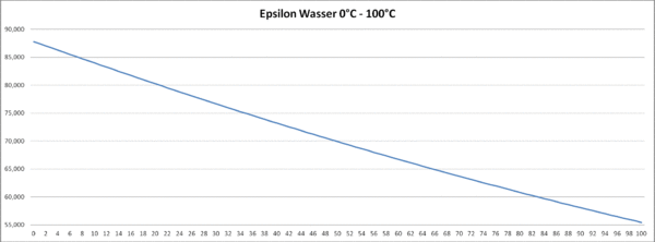
and the resulting permittivity graph
The frequency measurement is done using a ICM7555 timer-chip: 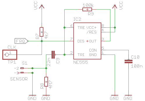
The electrode is attached to socket S1 and the frequency output (label FRQ) is connected to Port PD5 (T1 input) on the ATMega328. The complete circuit diagramm can be found here.
Arduino code
Temperature measurement
The temperature of the media is measured using a MAXIM DS18B20 integrated temperature sensor. Using this library the reading of 1-wire sensors is fairly easy.
OneWire  oneWirePort(ONEWIRE_PORT);
static DallasTemperature sensors(&oneWirePort);
static uint8_t oneWireAddr[8];
/**
  *  init the one wire bus
  **/
void setupOneWire(void) {
  sensors.begin();
  if ( sensors.getDeviceCount() == 1 ) {
    sensors.getAddress(oneWireAddr, 0);
  }
}
/**
  *  called from job framework every 10s
  **/
void doOneWire(void){
  if ( sensors.requestTemperaturesByAddress(oneWireAddr) ) {
    double t = sensors.getTempC(oneWireAddr);
    if ( t != DEVICE_DISCONNECTED_C ) {
      modBusRegisters.waterTemp = t;
    }
  }
The measured temperature value is directly written to the MODBUS registers. Have a look at my solution, how to put various datatypes inside MODBUS registers.
Frequency measurement
Frequency measurement is done based on a 100ms Tick from Timer2 and the count capability of Timer1.
Initialization
/**
 *  setup hardware
 *
 *  set timer 1 to count on PD5 port
 *
 **/
void setupWaterLevel(void) {
  pinMode(WATERLEVEL_PIN,     INPUT);
  // hardware counter setup ( refer atmega168.pdf chapter 16-bit counter1)
  TCCR1A = 0;    // reset timer/counter1 control register A
  TCCR1B = 0;    // reset timer/counter1 control register A
  TCCR1C = 0;
  // set timer/counter1 hardware as counter , counts events on pin T1 ( arduino pin 5)
  // normal mode, wgm10 .. wgm13 = 0
  TCCR1B |=  (1<<CS10) ;// External clock source on T1 pin. Clock on rising edge.
  TCCR1B |=  (1<<CS11) ;
  TCCR1B |=  (1<<CS12) ;
  TCNT1  = 0;    // counter value = 0
}
Measurement
This method is called every 100ms by Timer2 interrupt. To get the frequency in Hz simply multiply by 10.
/**
 *  This method is called inside the T2 interrupt
 *
 **/
void doWaterLevelCounter(void) {
  TCCR1B = TCCR1B & ~7;           // Gate Off  / Counter T1 stopped
  frequency = TCNT1 * TICK_RATE;  // convert to Hz
  TCNT1=0;                        // reset counter
  TCCR1B |=  (1<<CS10) ;          // External clock source on T1 pin. Clock on rising edge.
  TCCR1B |=  (1<<CS11) ;
  TCCR1B |=  (1<<CS12);
}
Calculation
This method is called every second outside the timer interrupts. It uses a simple moving average calculation over the last 10 values.
For frequency correction it uses the precalculared permittivity (epsilon) values from a simple array.
The calculated value is then written into the relevant MODBUS-register.
/**
 *  This method is called by the job framework
 *
 **/
void doWaterLevel(void){
  // put current raw value into moving average store
  putValue(frequency);

  // get the current average raw value
  double freq = getAverage();

  // get the temperature
  double temp = modBusRegisters.temp;
  uint8_t idx;
  if ( temp < TEMP_MIN) {
    idx = 0;
  }
  else if ( temp > TEMP_MAX) {
    idx = TEMP_STEPS - 1;
  }
  else {
    idx = temp;
  }
  double factor = EPSILON[idx];
  modBusRegisters.waterLevel = freq / factor;
}
First results of temperature compensation
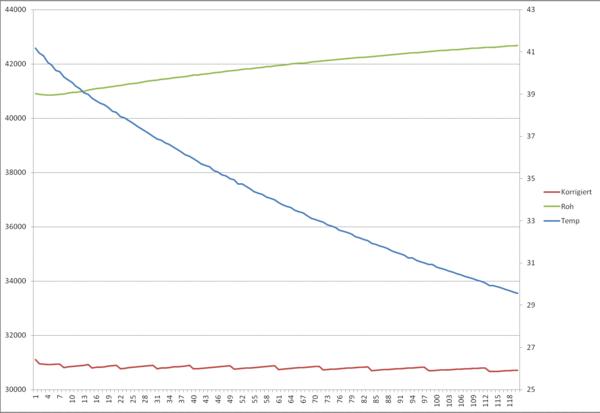
For this experiment I've placed the twin-wire electrode into water of abt. 41°C and measured the water temperature (blue line) as well as the frequency from the NE555 generator (green line) over a time span of 120 minutes.
The red line is the calculated water level compensated as described above - and as expected the compensated water level more or less flat. The small saw-tooths on the water level are due to the discrete compensation points (one per each °F) for the permittivity.

