Alle Informationen bezüglich vna/J sind auf eine neue Webseite umgezogen:
All information regardung vna/J is moved to my new site
In case you've bricked the UNO bootloader or even the USB bootloader in the ATMEGA16U2, this may help ...
For the main power distribution in my house, I also build a powersensor. The basic idea is the same as for this sensor. But the electric meter is already build into the distribution cabinet, so this power meter uses the so-called S0 bus of the power meter inside the cabinet.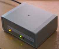
This is my first power/voltage sensor I've build. It is based on an commercially available powermeter from B+G E-Tech. You can find them on eBay or their website. It provides a 90ms pulse for each Wh flown through it.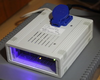
The line voltage is measured using a simple transformer and a circuit based on the schematic from OpenEnergyMonitor. The software to measure the line voltage is also from OpenEnergyMonitor embedded into my sensor framework.
My MQTT server also has some basic systems management capabilities - means the MQTT server can emit the following data to the MQTT broker:
- CPU temperature
- Power supply temperature
- Average CPU load
- Uptime of server
Since the beginning of my home automation project I made several tests to choose the right platform and right controller. I've done test with various sensor technologies etc. etc.
Most of the articels can be found in the Arduino category.
One decision was, that my webhost should be the main datastore for all data measured. With this decision, I've started to build a data collection and distribution infrastructure. The complete setup consists of two major components:
These components are detailed further down the page.
Some basic config stuff for the RASPI & MQTT
Last week I received my long awaited K-POD from QRP-Project in Berlin.
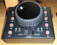
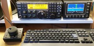
My proof-of-concept works pretty stable - please check the status screen:
Here I've build an audio CW-filter based on the circuit from NM0S/4SQRP.
This filter works pretty well. I've done some audio analysis using a cheap soundcard from BEHRINGER and the shareware application AUDIOTESTER.
Now I've finished the Audio CW-filter I've decribed here in details.
Hier eine Sammlung unserer Wanderungen/Ausflüge der vergangenen Jahre
Based on the work of John, M0UKD, I've build a small sensor-keyer. I used a surplus aluminium shelf and two aluminium stand-offs as "paddles".
See the evolution of this project here.
Lorem ipsum dolor sit amet, consectetur adipiscing elit, sed do eiusmod tempor incididunt ut labore et dolore magna aliqua. Ut enim ad minim veniam, quis nostrud exercitation ullamco laboris nisi ut aliquip ex ea commodo consequat. Duis aute irure dolor in reprehenderit in voluptate velit esse cillum dolore eu fugiat nulla pariatur. Excepteur sint occaecat cupidatat non proident, sunt in culpa qui officia deserunt mollit anim id est laborum.
This was my first participation in the WAG contest since 2010 - and I must say, it was a pleasure!
I managed to complete 472 QSOs all in CW :-)
I've planned to sell my ELECRAFT K2 so I placed some adds in the various HAM sources and I found a buyer willing give my K2 a new home.
Fortunately I decided to do a quick check on the K2 functions, to be sure, that the buyers receives a full functional K2.
I did the check in the late afternoon on 80m and I was shocked - strong stations can be received every 7kHz. Testing the transmitter shows a totally unstable RF signal.